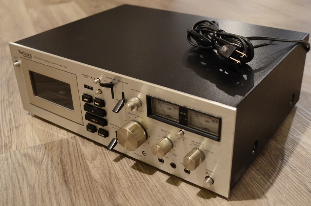
My post on attempting to hook up a remote to my Technics 676 (here) is by far the most popular post on my blog; it seems I have stumbled on a niche, and there is a general lack of fan material on maintaining this flagship product.
Maybe it’s because it was developed before Metal / Type IV tapes, so it does not support them; maybe it’s because it was designed to support Dolby FM, which itself became antiquated by the 1980s. As a “plain old” component deck, it’s a dependable tank with pinpoint recording control and a great look, with its flat brushed face and green-lit VU meters.
In my opinion, the majority of 676 units out there that do not work can be rehabilitated by replacing rubber parts, capacitors and resistors. This deck was built to last, and it shows everywhere – In the articulating bay door hinge, the logic board controlling loud solenoids, and most importantly its main components.
In 2024, this tape deck will be turning 50, and so the rubber parts on these units have oxidized. This affects the FF/REW function. In 2019 I replaced the main belt, but the FF/REW function was never good. This condition also barred me from using the memory function. I finally got around to doing this project, and I’m happy to report the unit is now back to original working condition.
The following is a guide to replace the idler tires on the Technics 676.
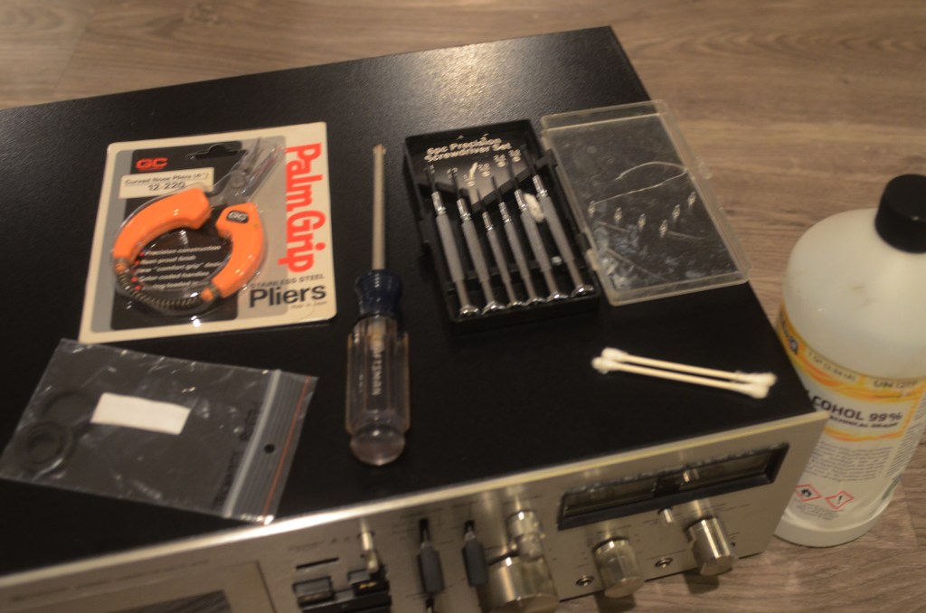
YOU WILL NEED a regular-sized Phillips head screwdriver (P2), a 2.0mm precision screwdriver, curved nose precision pliers, and three new idler tires. OPTIONAL 99% alcohol for cleaning the tape heads and a ribbed interface wheel.
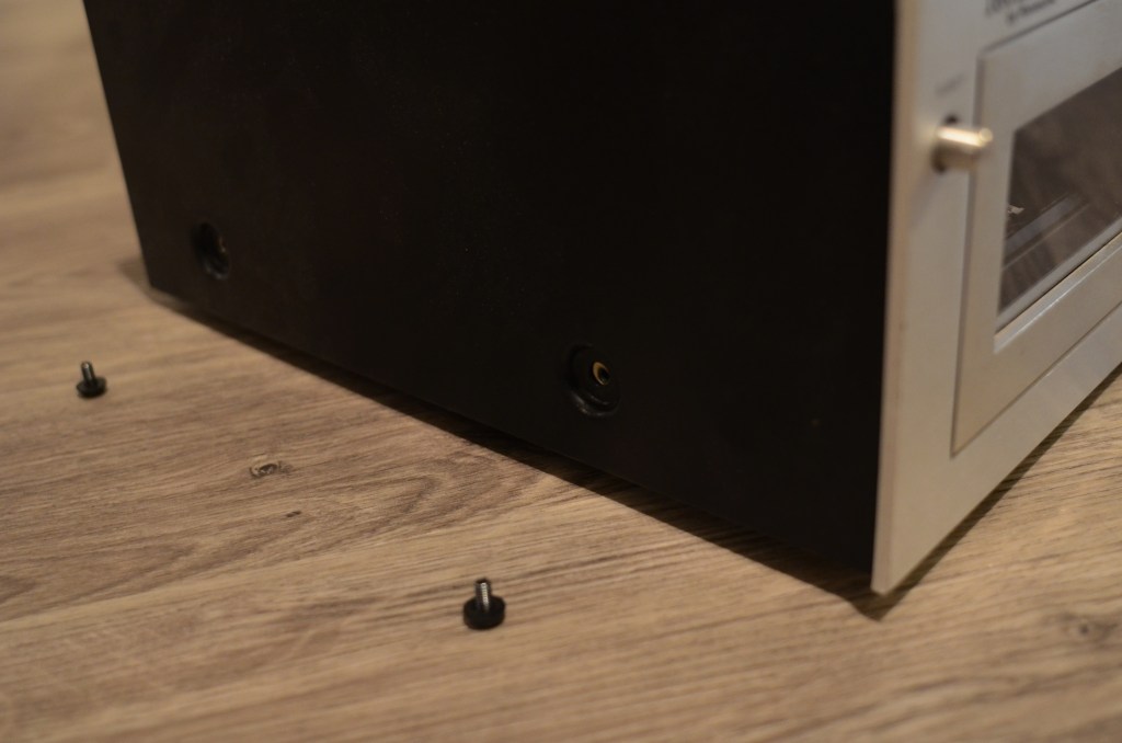
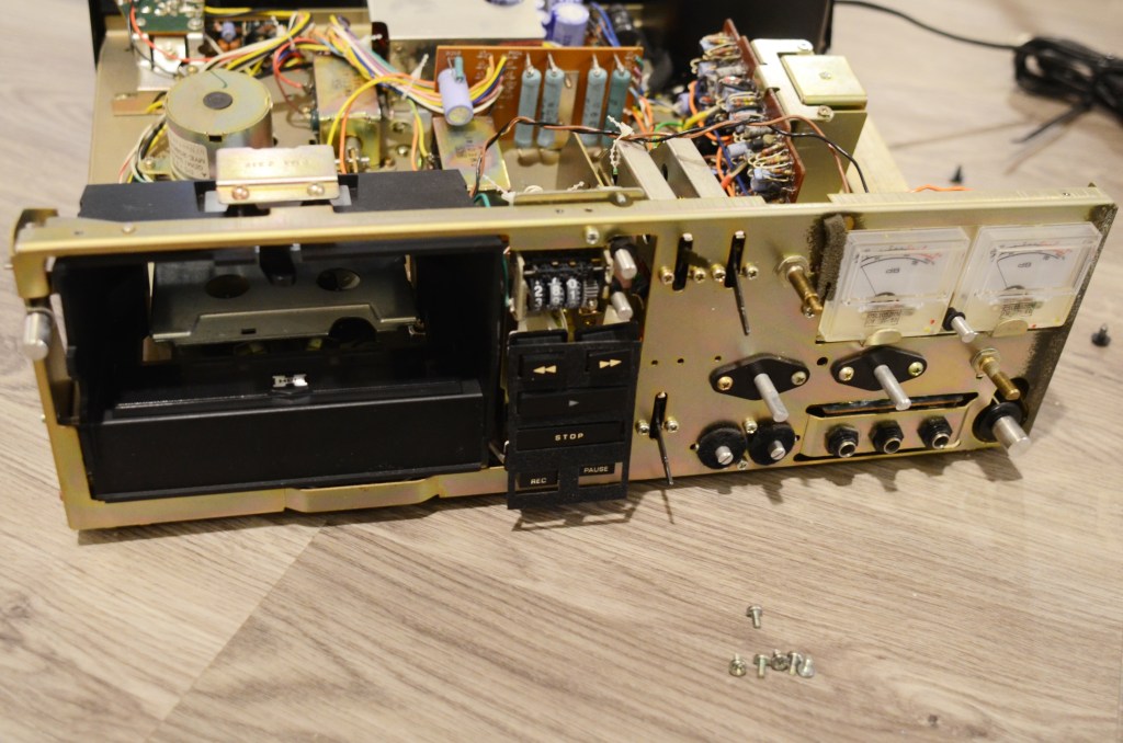
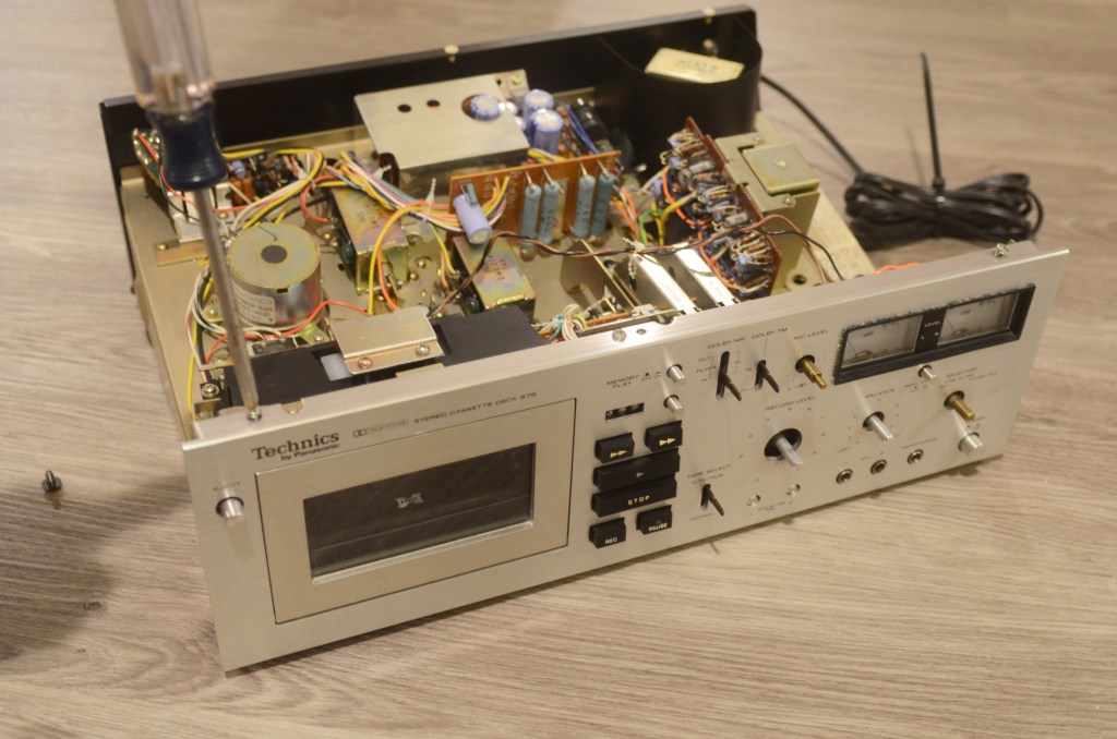
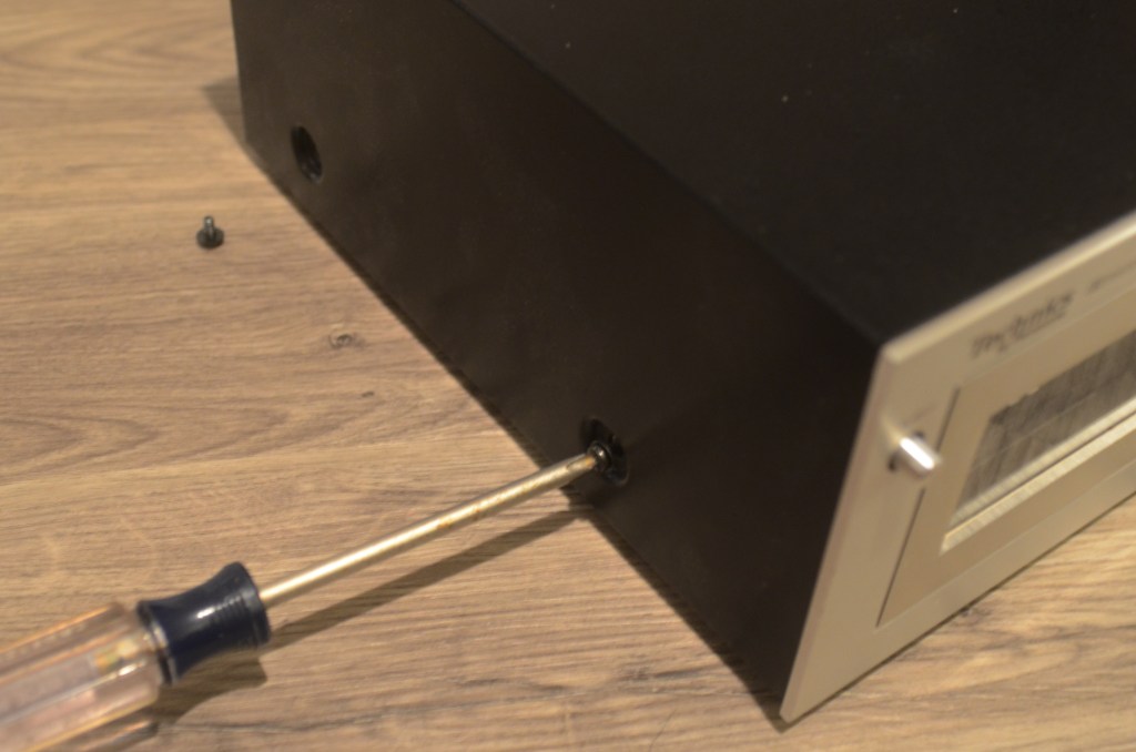
First, remove the four screws holding the cover. The cover is keyed to the face, so tilt it forward before lifting off.
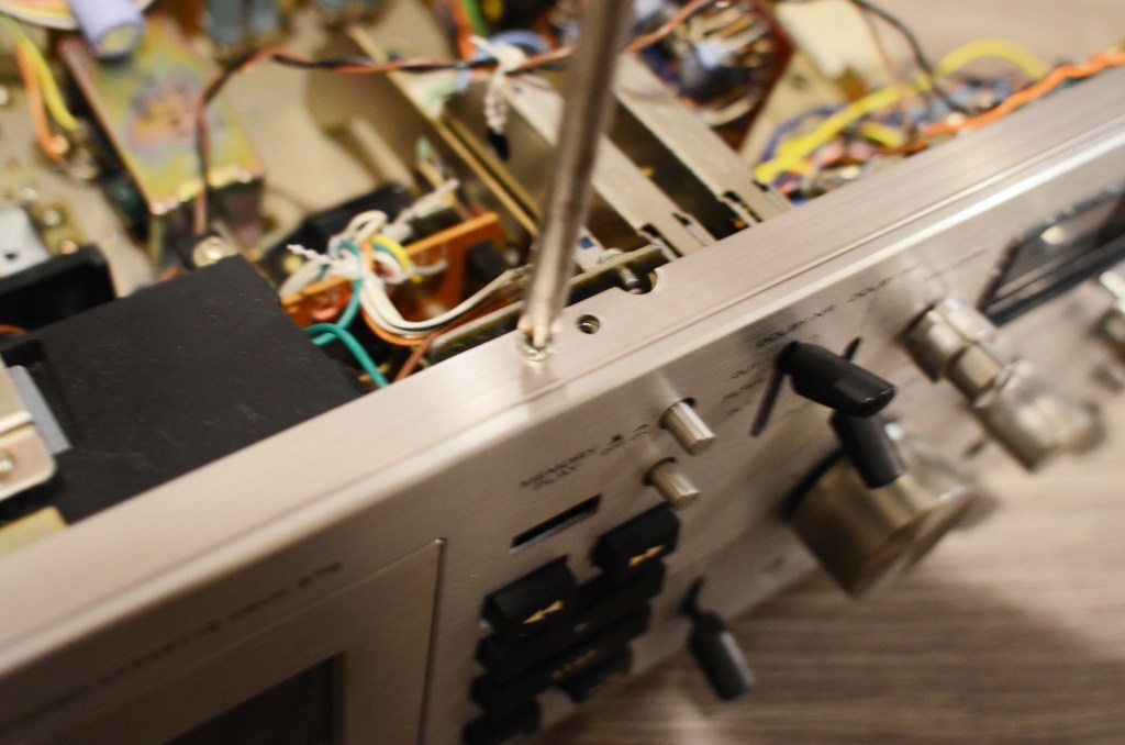
Take off six screws holding the face on.
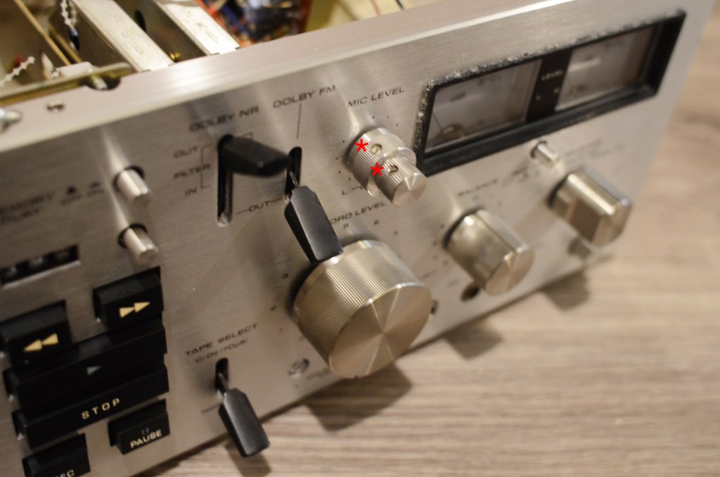
Take off knobs and switch covers. Use the 20mm precision screwdriver to remove the mic knobs.
Mind the delicate felt pad between the logic board and the face.
Remove four screws and eight washers from the cassette bay.
Remove two screws from the top lamp assembly. Remove plastic head shield in the bay.
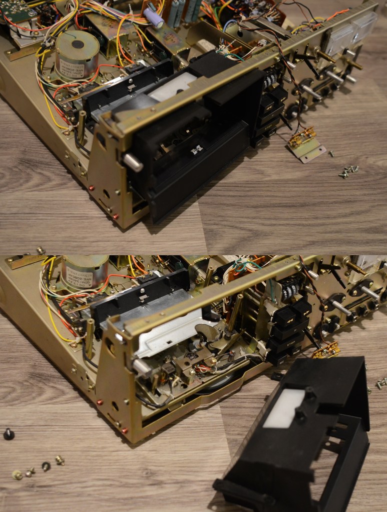
Carefully slide cassette bay through front of unit.
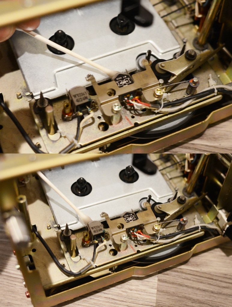
OPTIONAL Press down on cassette tray to expose heads. Clean the play and write heads with 99% alcohol.
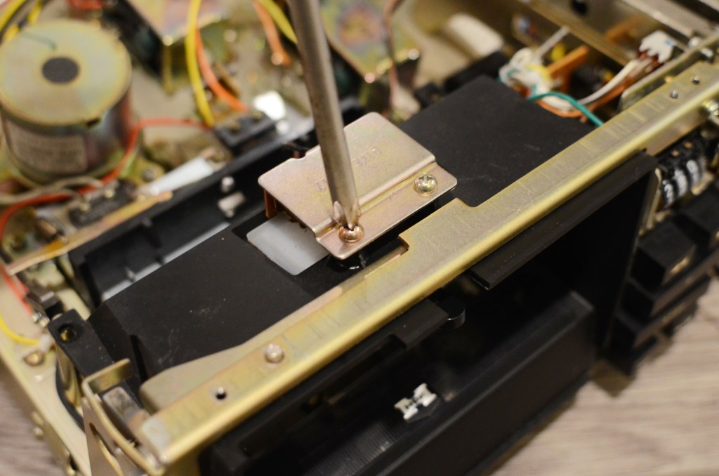
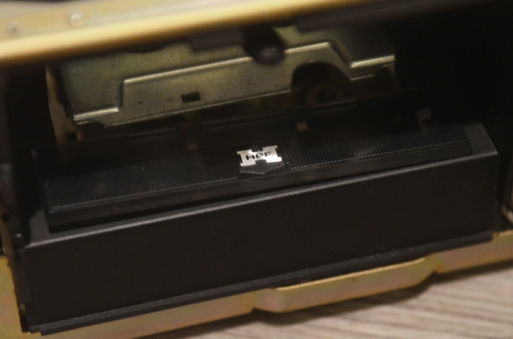
Remove four screws from cassette tray and flip cassette tray back over unit exposing FF/REW assembly.
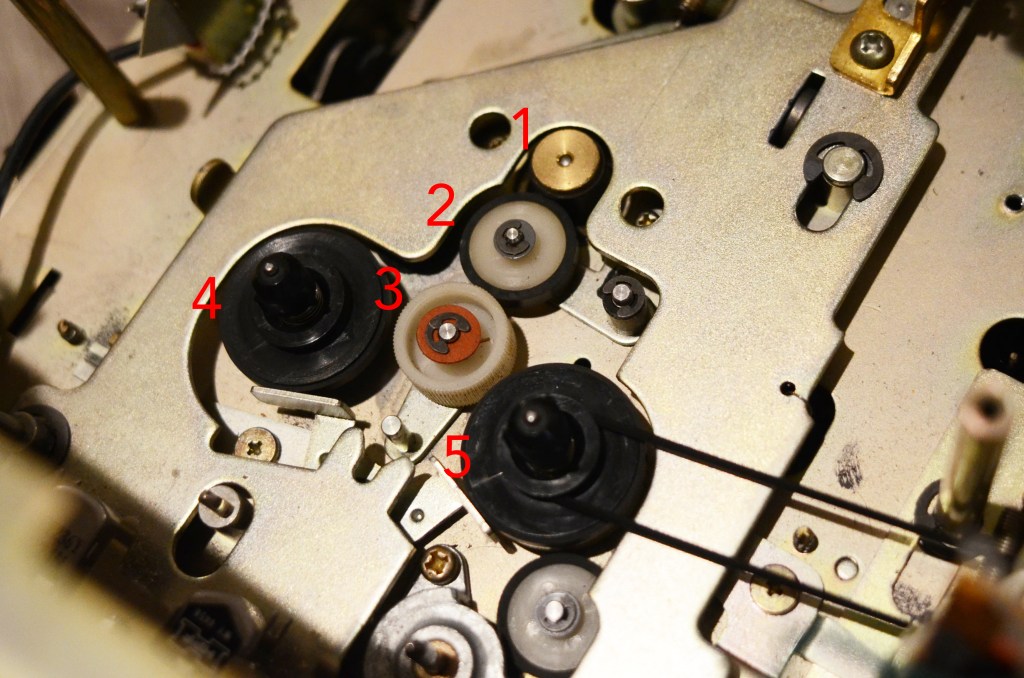
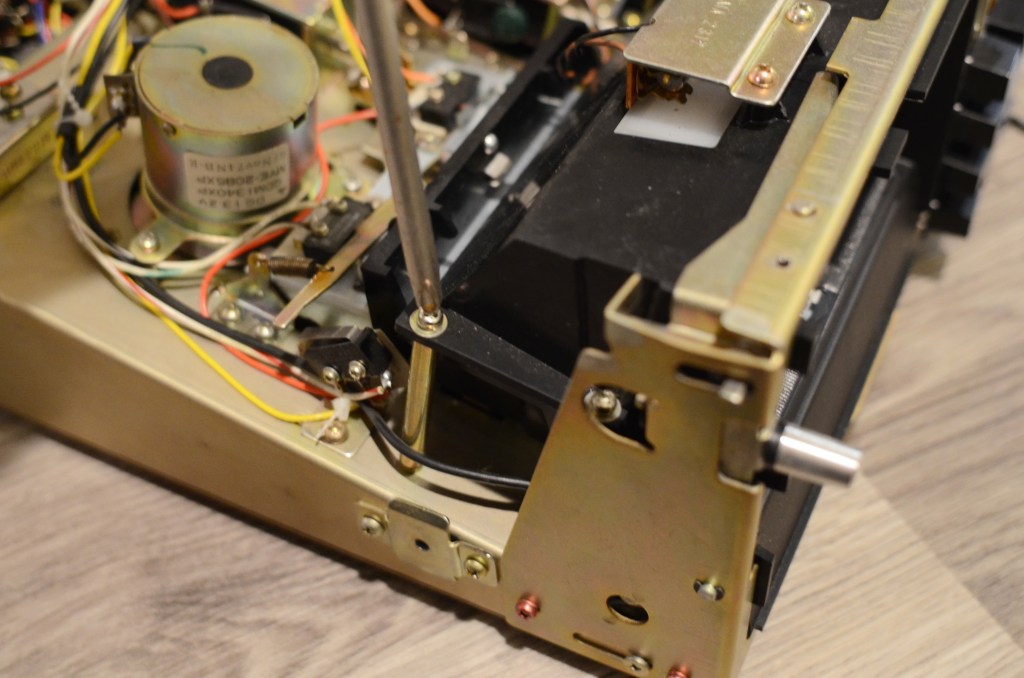
This is where the sausage is made.
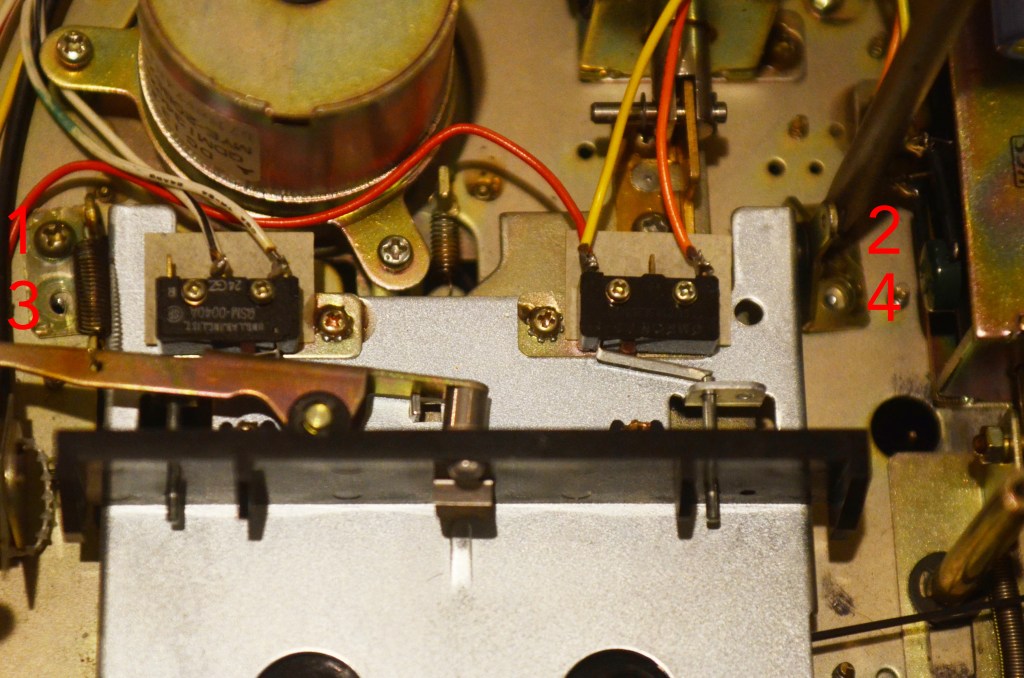
1) is the FF/REW-dedicated motor, 2) and 3) are interface wheels that transfer the motor’s movement to the two reels 4) and 5). Below 3) is a hinge allowing 3) to move left and right depending on the chosen FF/REW function.
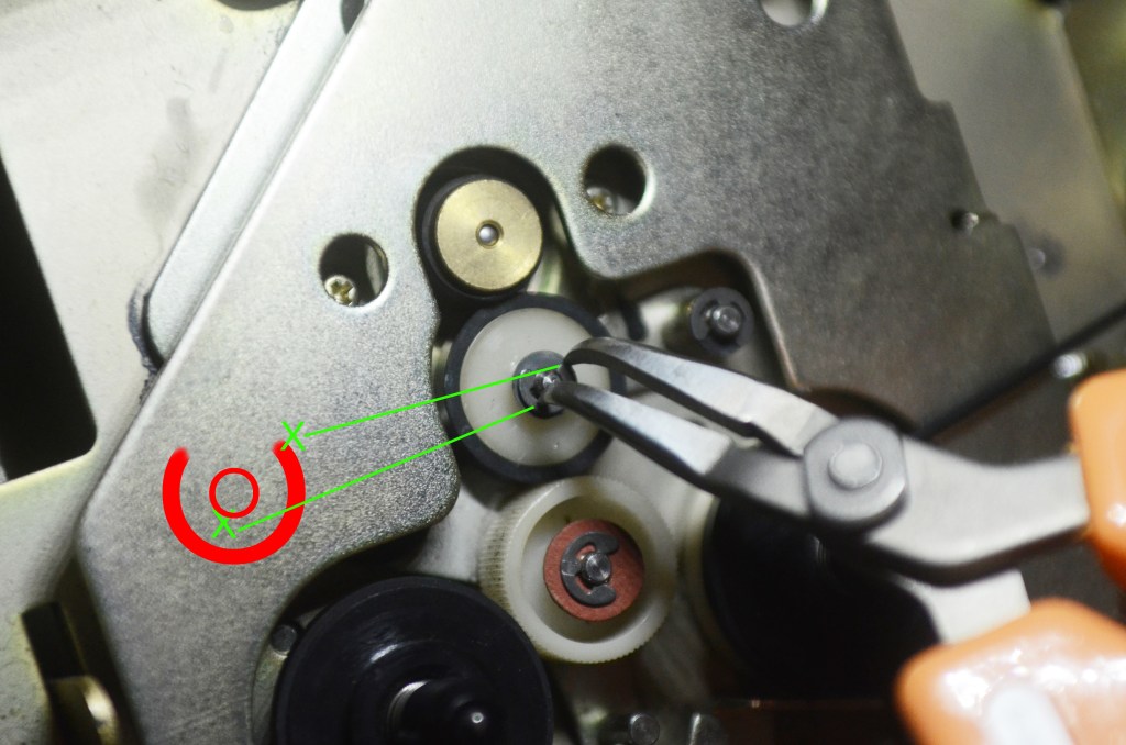
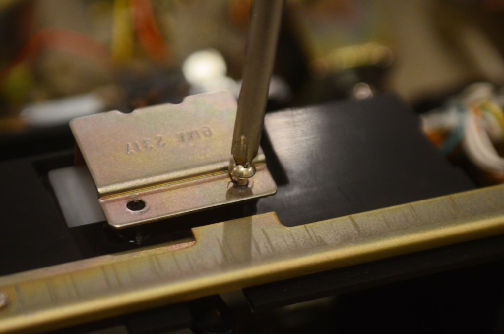
This is the hardest part of the job. Remove the Jesus clip with precision curved pliers. Align the tips of the pliers as illustrated, with one tip slightly off center on the center hub, and one tip on the edge of the clip. Squeeze gently. Remove washer.
The two contact points are not 180 degrees away from each other: Think ~160-165. If you do 180 deg, the clip won’t move; if you do 150 deg, the pliers will slide off and/or the clip will go flying, and you will quickly understand the etymology of this clip.
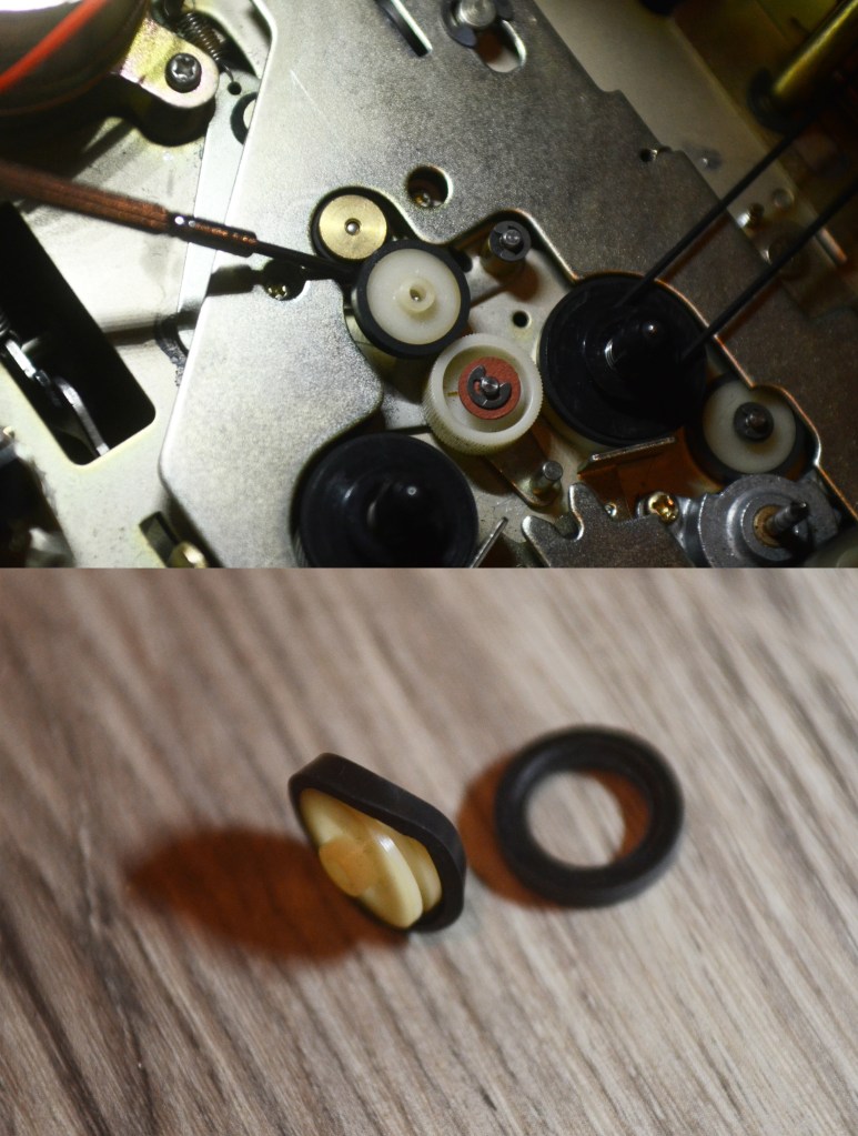
Use the precision screwdriver to remove the white wheel with tire. Remove and replace tire.
Here’s the deal with these 50 year old rubber tires: They don’t matter anymore. They do not need to be carefully removed. Use the precision pliers to grasp the other two tires from the reels, and remove and replace them. (Do be careful mounting the new tires!)
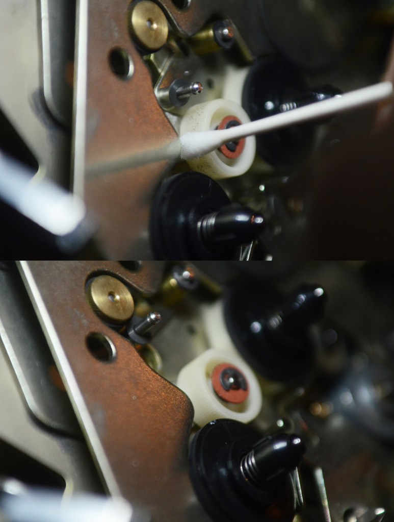
OPTIONAL This ribbed wheel has pieces of old rubber all over it. Clean it with 99% alcohol.
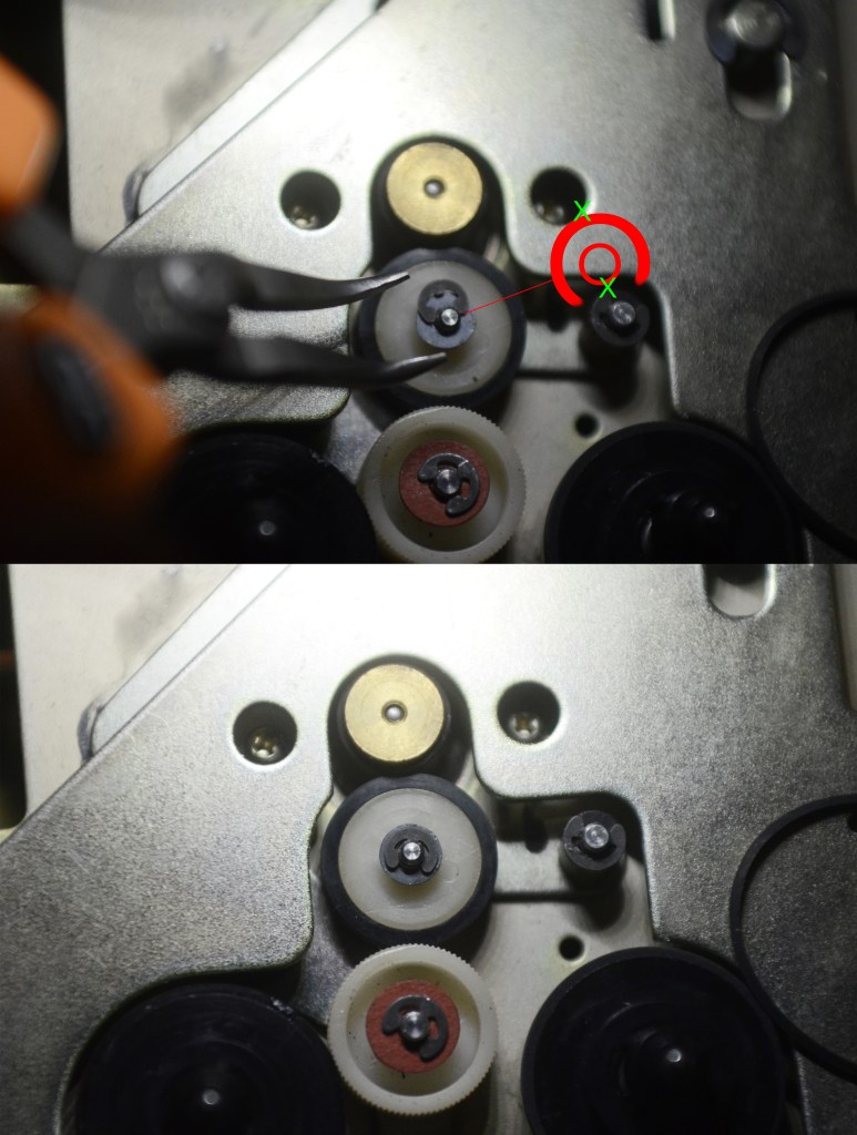
Replace the white wheel now with its new tire. Replace the washer and the Jesus clip. Align the pliers as illustrated, with the two contact points 180 degrees away from each other to reinstall.
The cassette tray mount has a lot of play during reinstall. To ensure correct alignment on the first try, install the four screws in this order.
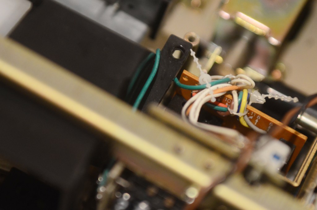
This is the second hardest part of the job. Slide the cassette bay back in through the front carefully, and mind lots of brackets and wires. I had to back it out again to move this green wire out of the way.
OPTIONAL If you want to replace the bulb at this time, the bulb is style XAMR9SHO.
Replace two screws in top lamp assembly.
Replace plastic head protector in the bay.
Replace six screws holding the face on.
Key cover into face and tilt into place. Replace four screws.
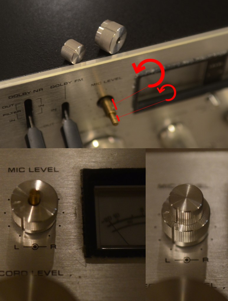
Most of the knobs are keyed, but the mic knobs are not.
Twist the inner shaft all the way to the left, then mount the knob (pointing at zero,) then screw it back into place.
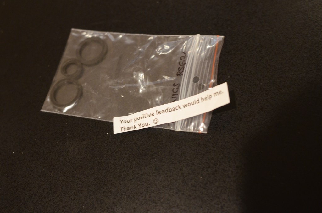
Shouts out to EBay seller SILICONEMIND for making these idler tires available. It is unclear if Panasonic still makes replacement tires, but this seller 3D prints exact replacements on good quality rubber. Thanks to SILICONEMIND for making maintenance of these vintage decks possible.
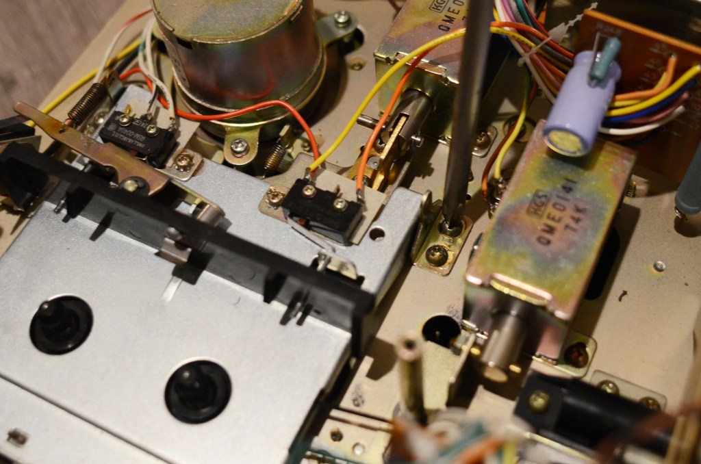
Keen readers will note that I re-installed the REW button on the logic board backwards! Oh no!!!! A reminder to do this job slowly to avoid breaking or scratching anything (and in my case, to avoid rework.) To finish a job and notice a screw or two on the floor next to you is devastating! Keep a towel or blanket nearby to safely store the outer case, front face and pile of screws while working.
Thanks for reading, and enjoy!

Hello,
Good photography, which is very important.
This is a lovely laid out deck, it’s very tempting to try one of these out as a project. However, I have about 30 decks (yes, ‘thirty’) and two reel to reel machines. All repaired; it’s an addiction! :o)
Regards,
Eric.
LikeLiked by 1 person